In part one of this series I covered my inspiration for the trench table, planning, making a hexagon template and cutting out the blank tiles. Once I had cut out a suitable backlog of hexagon sections I started thinking about landscaping. I picked some pretty low jeopardy tiles to start with – edge sections without trenches or simple trench sections that if I cocked up would not cost a great deal in lost time or effort.
For the trenches, I decided the basic cross section at the tile edges would be 20mm deep (i.e. one thickness of insulation foam – nice and easy) 40mm wide at the base of the trench, and 50mm wide at the top. This would allow figures on 32mm bases to easily traverse the trench.
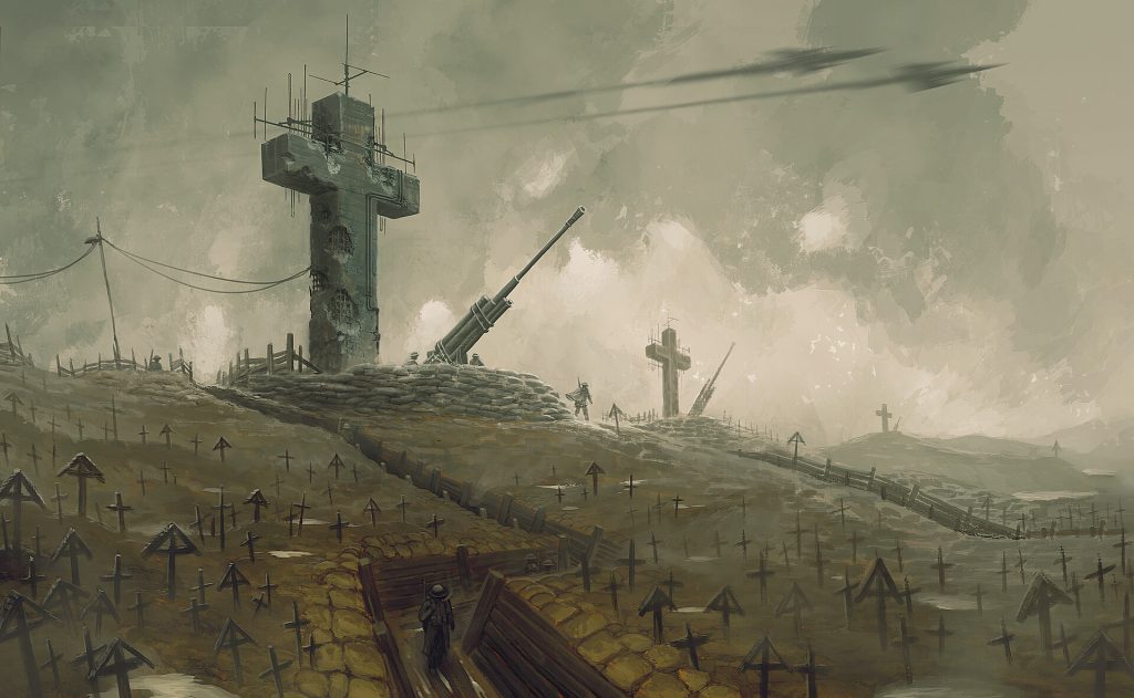
As an aside, although I introduced this project as a Trench Crusade inspired one, and certain features I had in mind such as a the concrete cruxific emplacement are very specific to that game, I certainly intend the finished table to be usable for 40k, Kill Team and more.
Something that is probably rather obvious is that all cross sections at the tile edges must be identical and located in the centre of the respective hexagon edge, so that they would meet up neatly with the next tile. Equally, any undulations in the surface level of the ground at the tile edges would have to be perfectly symmetrical and identical on all tile edges.
Either that, or you, like me, opt to keep it very simple and go for zero undulations at the tile edges.
Here are the fruits of my first labours:
I know what you’re thinking – that looks a bit shit doesn’t it?
You’re not wrong. And I made several tiles in the same vein. And then I lost interest for about three months because the tiles didn’t inspire me to take the next steps.
Here’s the issue as I see it. Cutting a flat bottomed trench through an otherwise largely flat and featureless landscape doesn’t look like a prototypical WW1 battlefield, at all. I’d have to make some concessions to wargaming practicality, but at root I wanted to make a diorama quality battlefield (you’ll recall it’s why I set out to make deep, hexagonal tiles with fully modelled trenches instead of the simpler approach of arranging areas of raised ground on top of a battlemat). But I had not studied my source material, nor looked at how other diorama level hobbyists tackled trench scenes.
Luckily I did get my mojo back and the breakthrough came over Christmas watching a couple of YouTube videos on WW1 dioramas, especially this one by Modelite, where he uses a small heatgun to burn a natural undulating shellpocked surface to the no mans land section of the diorama.
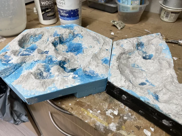
Lacking a heatgun, I tried to see what would happen if I used a lighter, and got pretty comparable results. I worked out that I could start by cutting and gouging out the major features that are dug down into the tiles (trenches and major craters), and then finish off with the lighter to put small shell holes and undulations across the piece – just being very careful to avoid the tile edges which must remain uniformly regular.
This neatly takes care of the dug down features. After that, using sculptamold or modelling clay or something similar, I could build up the landscape above the level of the tile. Notably, I found building ridges of earth around the craters very effective, along with other random hillocks and rises.

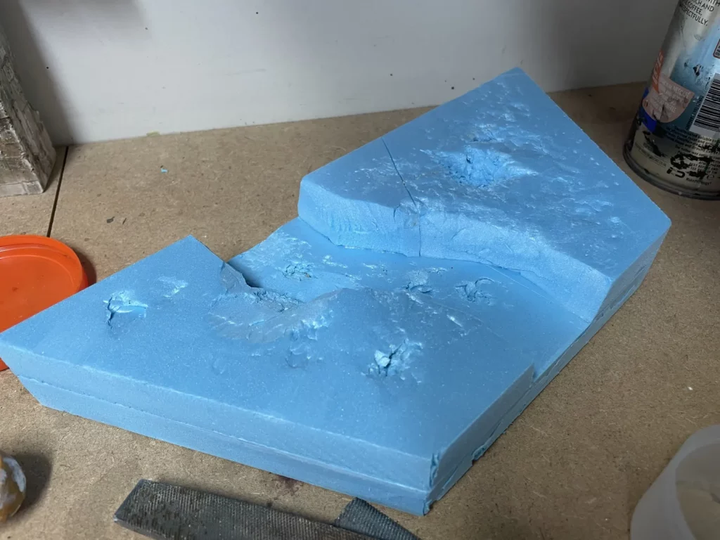
It wasn’t long before I started to also add bigger inclines with wedges of insulation foam before cutting in the craters and trenches. After all, the full hexagonal tiles have a span of 30cm between the points and about 26cm between the flat edges. Only the edges need to be 2cm. Between those edges, anything could happen.
If I return to my original inspiration, one of the effects I rather like is the sense that the crucifix emplacement is on a hill, with trenches descending from it down the hill.
To get this effect on my tiles, I would need to make full use of the thickness available to me – increasing the height of the tile as much as possible beyond the normal 40mm thickness where the emplacement sits, and having neighbouring tiles where the ground descends well below the normal tile thickness. In practical terms, I figure a 4-5cm difference could be achieved between the peak and trough on two tiles arranged side by side, which I’ll have to hope will be enough. It should certainly allow the hill tile to legitimately block line of sight to models behind it, creating an interesting gaming challenge.
The next days proceeded in a feverish frenzy of hacking up and gluing together insulation foam, burning through lighter fuel and happily slapping on sculptamold, so much so that I totally neglected to take any photos of the steps I’m describing. That will have to wait for a new tile that I promise to document in more detail.
Next up though – ground textures.