This journey started at RMWeb. Being somebody with zero experience in model railways I needed to seek out the experts and my research quickly showed me that the forums there were full of people who not only knew what they were talking about but were more than willing to help people out not just with pointers or advice but by actually designing track layouts to meet specifications. Consequently I started a thread there and thanks to several members had quickly got a track plan that met all my requirements. Suffice to say that I would strongly recommend anyone on the same boat do what I did and join RMweb for help.
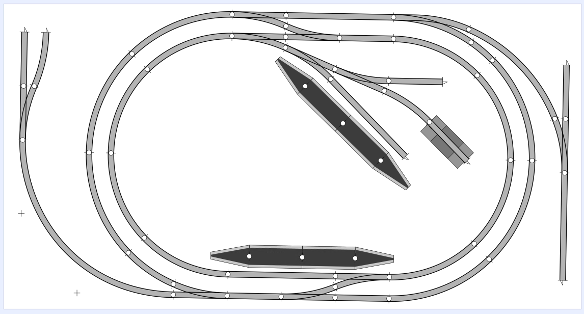
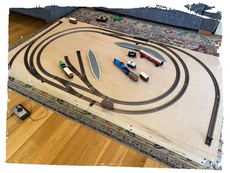
I won’t linger on the layout design process as you can read all about it on my RMweb thread but this layout meets the requirements I had, namely it fits on a 95cm wide board i.e comfortably under a single bed for storage, it has two separate loops so both boys can play at the same time, and a bit of variety in terms of what can be done, there being two stations, room for an engine shed and a few sidings to play with which could become storage sidings, docks, goods yards or what have you – all to be determined at this stage.
I also knew going in that I wanted to have a track layout with changes in elevation for the track. This would make the layout a bit more fun to operate and add modelling interest. I took a lot of inspiration (and advice) from RMWeb member Kris and his under bed 00 train set. Before seeing this, I’d assumed that any and all contouring of the layout would be achieved by building up from a flat sheet of ply, probably using insulation foam. Kris’ layout showed me an alternative way to approach this, by actually varying the height of the ply by cutting it strategically and then screwing it to a frame of varying height.
The advantages of this are fourfold:
- The inclines and declines are smoother and more natural than could ever be hoped for with hills made with insulation foam later. This means less derailing, smoother driving and better conductivity at joins between tracks.
- Track can be screwed directly to the plywood at all points, rather than needing to be secured to insulation foam which would of course be weaker. Again, this is important for the consistency of the train driving experience and conductivity.
- The underside of the track is more readily accessible if needed (principally for wires), without needing to dig out voids in the foam, as you only need to go through the ply.
- The surface of the layout is much stronger and resistant to wear and tear compared to one built from foam or other materials. With the majority of the surface being solidly supported ply, I’d be comfortable if the boys started walking over or sitting on the layout, which I’m sure they will do at some stage – as opposed to a foam built landscape where I’d constantly be worried about features being crushed and resulting damage or faults to the actual rails.
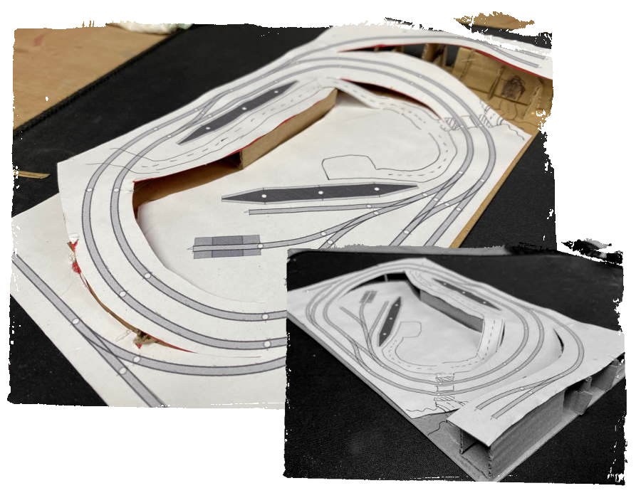
With all these benefits I think the additional thinking and complexity at the baseboard stage is well worth it. I spent several hours in the early morning trying to work out in my head how to build the underlying frame to make the contours I had in mind work. In the end I printed the layout and built a quick maquette, which cleared things up and showed that there weren’t actually that many parts of the frame that needed to be higher to achieve the 3 tiers and the transitions between them.
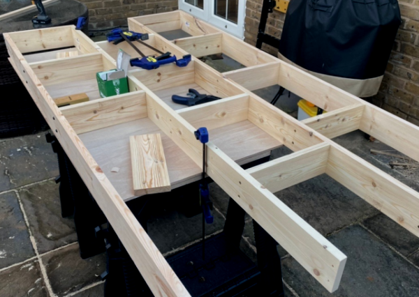
Still, rather than trying to anticipate precisely the height of each part of the frame in advance, I decided to build a flat frame that I would then add risers to later on. This flat frame was a simple affair built from PSE whitewood and naturally trying to keep everything as square as possible, using clamps to help with screwing everything together. With one eye on how this would look once stored away, decorative black phillips head screws were used on the long edges.
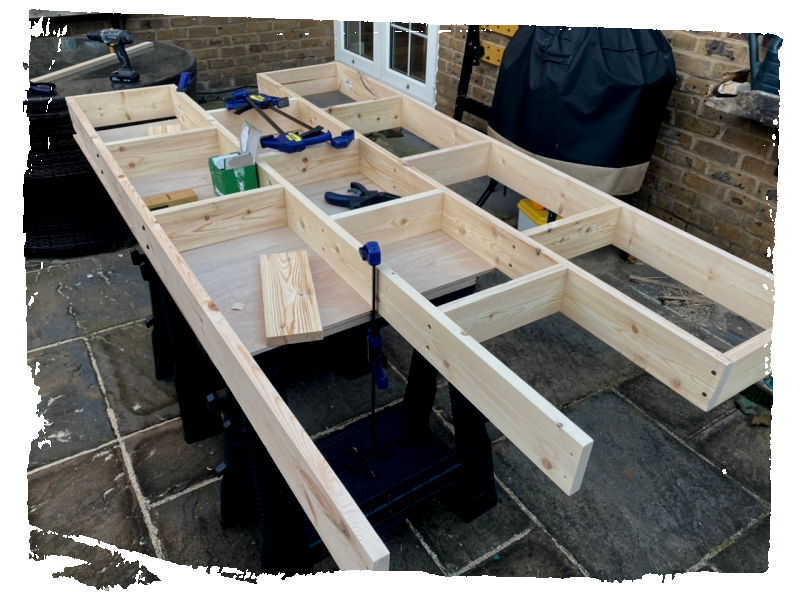
Since I used quite wide (94mm) timber to build this (for strength purposes), during construction I decided it would be useful and interesting to make use of some of this depth to build a couple of drawers into the frame. This is why the central void in each short end of the frame is not closed off with a timber strut, as a small drawer will later be built there. These drawers can be used to store engines and carriages not in use.
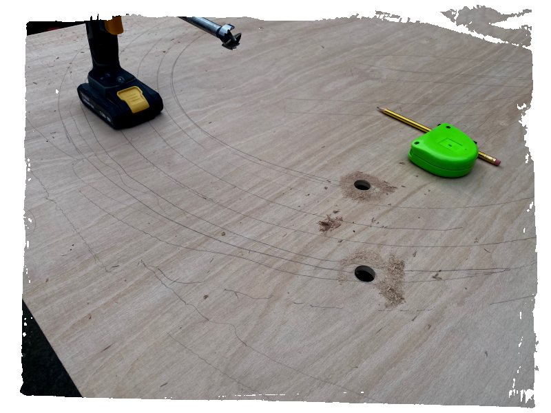
The next stage was to lay out and test the track, ensuring everything would work electrically and space wise as planned. It did, and we took the opportunity to draw the outlines of all parts of the track onto the plywood.
With this done I could see precisely where to cut the plywood. I started with 3/4″ holes drilled with a forstner bit at the point at which each incline or decline begins and ends. These holes act as access points for the jigsaw but also allow the plywood to flex more at the point where most of the stress would occur – hopefully preventing any splitting of the wood. The rest of the cuts are simple jigsaw cuts. I have to admit to being skeptical of whether this whole approach would work, right up until the cuts were made – then I could see how willingly the plywood bends and flexes once it’s cut to 6-8″ wide (the maximum width of any stretch of wood I would be asking to make an incline).
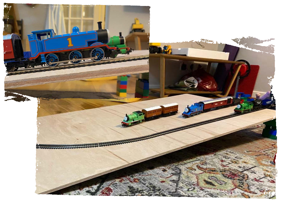
Another important test was working out what sort of gradients the engines could safely traverse. To do this, me and the boys spent a happy hour with a sheet of plywood resting on duplo blocks, increasing the height block by block and driving Thomas and Percy up and down, pulling and shunting, until they reached the point of failure. We found out that Percy could manage up to around a 7% gradient and Thomas a mighty 16% before they started to wheelspin and slide down the incline. I then took these figures to Excel and with the length of the relevant runs of track in hand, calculated the change in elevation for each run at 6%. This turned out to be much higher than I needed, as 6% would imply a total gain of around 11cm from the lowest to highest point, which I don’t actually have space for under the bed.
With that done I made one riser to run most of the length of one board edge, and we screwed the base board to it and to the frame itself. This created the gradients that the main track oval runs over.
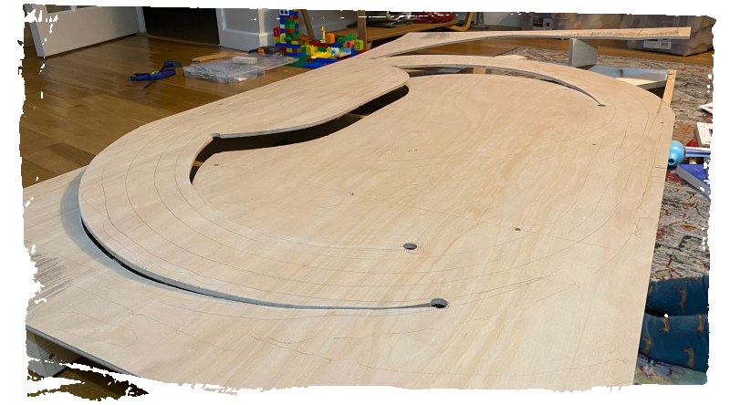
I then flipped the board over and screwed in additional small risers into the frame, butting them up against the underside of the gradients and the highest point of the board, and turned it back over to screw the board down against these small risers.
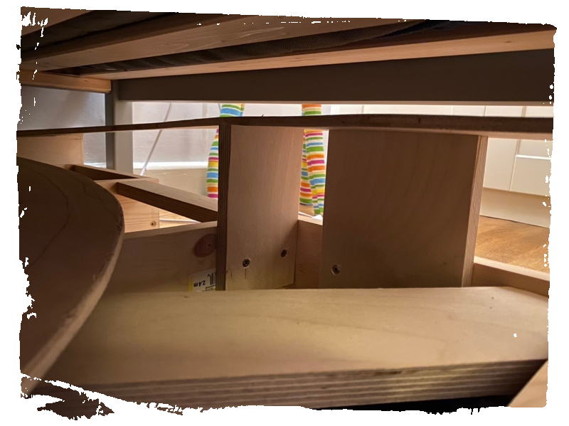
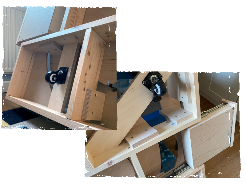
The final job on the basic baseboard construction was to add some castors for ease of sliding the layout in and out from the bed, and slot in the drawers which are just simple plywood things made with butt joints, a 3mm MDF base and a fascia panel that matches the rest of the frame, attached with cheap metal drawer sliders. In these photos you can see all of that and more of the risers that make the contoured board possible.
Next, on to ballasting and track laying…