Last night and this morning I started the process of making a mould of the finished part. Since I’ve also finished the shuriken catapults I decided to cast these at the same time, after all, we will generally need both for a single jetbike (actually that’s a rubbish reason as we’ll also need fins and maybe a couple of other things, but I couldn’t wait to finish those before mould making!)
Here’s a step by step of the process I’ve been through so far.
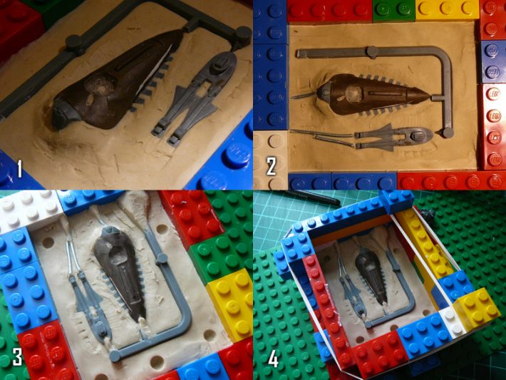
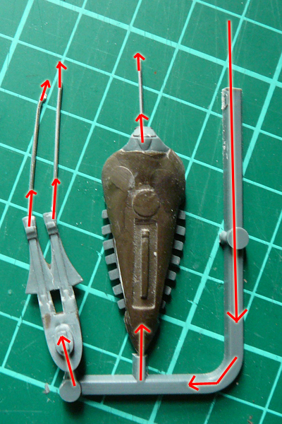
First, planning. I’ve learnt from reading various other plogs involving casting that this is very important. You need to be able to predict where air will accumulate in the mould and try and prevent that from happening by orienting things so that there are no air traps and where there are, there are escape routes for the air. After some thought this is what I think is the best layout of the sprue for these two parts. Resin will flow down the large pouring hole on the right, fill the parts from the bottom up expelling air from the vents as it does so.
As it is, I still expect there to be various problems that will need fixing, notably on the underside of the shuriken catapults where there is a possible large air trap that I couldn’t run an escape route from, and on the vanes of the canopy part which are just uncredibly fiddley.
Next I made a mould box out of lego to a size that leaves approximately 1cm around the sprue. This was filled with a layer of plasticene which was compressed and smoothed into the corners of the box, before the parts were pressed into the plasticene as per the plan.
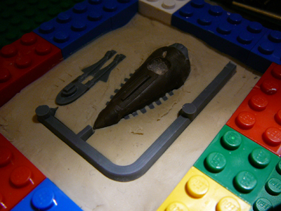
Next we have to think about how the mould will separate and where the mould lines will be. The surface of the plasticene will be where the mould line appears (click for a full sized image):

- Because the canopy part has a large undercut below the control panel the surface of the plasticene needs to be built up around this part, otherwise the part will be impossible to extract from the mould. Also note that I am trying to set the mould line at a level at the top of the vanes. Equal consideration was given to the catapults where the mould line is at the top of the catapult body. These areas seem easiest to clean the mould lines off later.
- I add garden wire where air vents are required.
- Here I’ve used more plasticene to fill out the air vents/pouring channel, connecting them properly to the parts and funnelling the entrances and exits out at the top edge of the mould. Also at this stage I went around the parts carefully with clay shapers, ensuring the plasticene was flush with all surfaces and cleaning excess plasticene off the parts themselves.
- Finish the box by building it up higher with lego. Again you need around 1cm above the parts. I found it useful to wrap an elastic band around the lego to keep the box tight and minimise rubber leaking through the gaps between bricks.
Finally we’re on to the pouring of the first half of the mould (click for a full sized image):
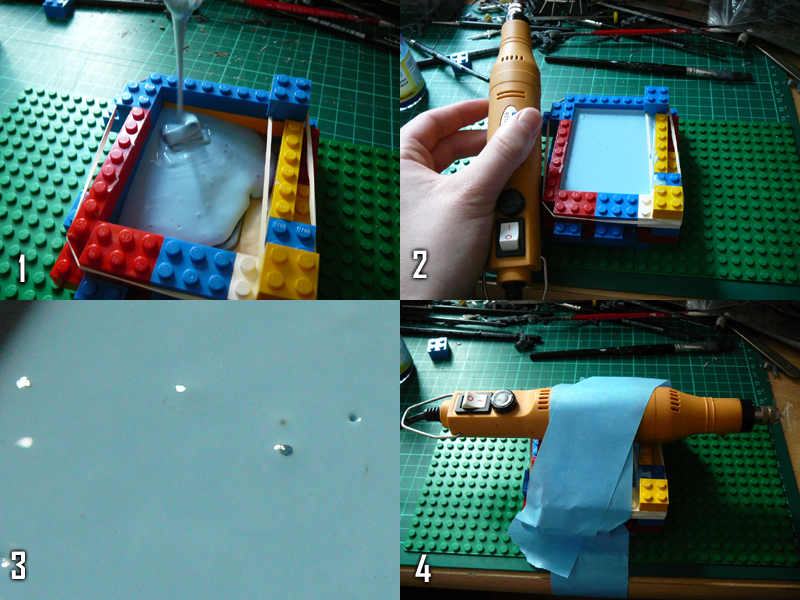
- Mix the rubber per the instructions, and then pour in a slow steady stream, from one corner only. The rubber flows naturally around the parts, pushing the air ahead of it as it goes.
- A more professional mould making process would involve a vibrating table of some sort, which helps to dislodge any air bubbles in the rubber that are clinging to the parts. As I don’t have one of those, I put a lopsided weight in my dremel type thing (a piece of bent wire) to make it vibrate and then held it against the mould box.
- Lots of air bubbles started popping to the surface.
- Eventually I got bored and taped the drill to the box and left it for 5 minutes or so.